Every engineer engaged in fluid power or process control will eventually encounter solenoid valve symbols on the schematic. Quickly and accurately understanding the meaning of the symbol is one of the most practical skills in mechanical, pneumatic and hydraulic engineering.
The solenoid valve symbol is a standardized graphical representation method used in engineering drawings to describe how the valve controls fluid flow. Engineers do not have to draw realistic components, but use a simple symbolic representation to encode the number of ports, the number of positions, the driving mode and the default state of the valve into a simple icon, so that it can be perfectly integrated into the circuit diagram.
This guide covers all major solenoid valve symbol types used in pneumatic systems and hydraulic circuits.
What are Solenoid Valve Symbols?
Solenoid valve symbols represent functional states using adjacent squares (one per position) with flow arrows, a coil (zigzag/rectangle) for actuation, and a spring for return. A 2/2-way normally closed (NC) valve shows a blocked path in the rest state (right box), while 3/2-way valves control flow between three ports.
How to Read the Solenoid Valve Symbol?
All directional control valve symbols, including solenoid valves, are composed of the same visual elements.
Boxes (Positions)
Each square box in the symbol represents a switching position of the valve. The two boxes indicate that the valve has two positions; three boxes indicate that the valve has three positions. Draw the boxes side by side.
Arrows and flow path
In each box, the arrow indicates the direction of the fluid flowing through the valve when the valve is in that position. Arrows pointing to each other (in the T shape) indicate port blockage. The straight line through the valve indicates a smooth flow path.
Port lines
A line extending outward from the bottom (and sometimes the top) of the symbol represents the physical connection point of the valve’s port-pipe or fitting. The number of ports corresponds directly to the way identification of the valve.
Actuator symbol
At one or both ends of the valve symbol, you will see the actuator symbol. For the solenoid valve, the symbol is represented by a small rectangle with a diagonal line (in the circuit diagram, the letter Y is usually followed by a number). At the other end, you will usually see a reset spring symbol – a serrated line that represents the spring reset mechanism.
Reset (default) position
The box next to the spring symbol always shows the default or power-off state of the valve. This is the position of the valve when no electrical signal is applied. Therefore, it is important to identify the stationary position when interpreting the symbols of hydraulic solenoid valves or pneumatic solenoid valves (for safety-critical applications).
The 7 Most Common Types of Solenoid Valve Symbols
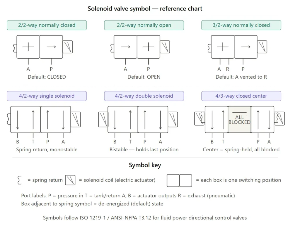
2/2-way normally closed (NC)
Notation: 2/2-way NC
What it means: 2 ports, 2 positions, default = closed (no flow)
This is the most basic solenoid valve symbol. The fluid channel is blocked at the stationary position. The solenoid valve moves the valve and opens the fluid channel after energizing. This valve symbol is widely used in fluid-controlled switching applications such as water dispensers, medical equipment and irrigation systems.
Symbol reading: a box shows the blocking arrow; the adjacent box (energized position) shows the through arrow. One end is the solenoid valve symbol, and the other end is the spring symbol.
2/2-way normal open (NO)
Notation: 2/2-way NO
What it means: 2 ports, 2 locations, default = open (flow passes)
The symbol of the normally open solenoid valve indicates that its working principle is opposite to that of the normally closed (NC) solenoid valve. When the power is off, the fluid can pass freely. The solenoid valve closes the circuit after energizing. This configuration is suitable for applications that require fail-safe, such as cooling water circuits for industrial machinery. The fluid can still continue to flow after power failure in these applications.
3/2-way normally closed
Notation: 3/2-way NC
What it means: 3 ports, 2 positions, default = inlet block, outlet vented
This is one of the most common pneumatic solenoid valve symbols. The three ports are usually marked as P (pressure supply), A (actuator/output) and R or T (return/exhaust/vent), respectively. In the reset position, port A is connected to the exhaust port. After energizing, P is connected to A to pressurize the actuator.
This valve symbol is the standard symbol for controlling single-acting pneumatic cylinders.
3/2-way normally open
Notation: 3/2-way NO
What it means: 3 ports, 2 positions, default = pressure output
In the reset state, the pressure (P) flows to the actuator (A). After energization, A is connected to the exhaust port, and P is blocked. Although not as common as normally closed (NC), it is very important in specific fault safety or process control scenarios.
4/2-way single solenoid
Notation: 4/2-way, spring return
What it means: 4 ports, 2 positions, one solenoid actuator + spring return
The schematic symbol of this solenoid valve contains four ports: P (pressure), T (tank/return), A and B (two actuator outputs). It controls the double-acting cylinder or motor by controlling the flow to both sides. A single solenoid valve moves the valve from the static position of the spring reset to the energized position.
Key visual cue: the symbol shows two boxes, one end is a solenoid valve, the other end is a spring.
4/2-way double solenoid
Notation: 4/2-way, double solenoid (bistable/impulse)
What it means: 4 ports, 2 positions, one solenoid on each end, no spring center
This symbol is composed of two boxes and two ends of the solenoid valve symbol, no spring. This is a bistable valve: even if the solenoid valve is powered off, it will remain in the last position to be driven. This is crucial in applications where the valve position needs to be maintained during power outages.
4/3-way with center position
Notation: 4/3-way (open, closed or tandem center)
What it means: 4 ports, 3 positions, spring-centered
This is the most commonly used and most complex hydraulic solenoid valve symbol. The middle box (center position) represents the default static state of the valve, which is fixed by the springs at both ends. There are three configurations in the center position:
- Open center: All ports are connected in the middle, allowing free circulation
- Closed center: all ports are blocked in the middle, keep the cylinder position
- Tandem center: P is connected to T, while A and B are blocked, reducing the load of the pump.
The visual characteristics of this valve are: both ends with a solenoid valve symbol, each solenoid valve and the outer box between the spring connection, forming a three-box layout.
Solenoid Valve Symbols in Pneumatic System vs. Hydraulic System

Pneumatic solenoid valve symbols usually appear in the circuit using compressed air (5-10 bar). The outlet leading to the atmosphere is usually represented by a triangle or opening line. Pneumatic circuits usually use 3/2 and 5/2 valves to control the cylinder. Due to the compressibility of air, the difference between normally open (NO) and normally closed (NC) has little effect on the pipeline pressure.
Hydraulic solenoid valve symbol appears in a system where the working pressure is much higher than the pneumatic system (up to 350 bar or more). The T type interface returns the pressure back to the gas storage tank rather than directly discharged into the atmosphere. In the hydraulic symbol, sometimes a dashed line is used to represent the leakage path (internal and external tubing), while there is no corresponding dashed line in the pneumatic diagram. The 4/3-way valves are more common in hydraulic systems due to the need to precisely control the double-acting actuator and maintain its position.
Choosing the Right Valve According to the Symbol
| Solenoid valve symbol quick look-up table | ||||
|---|---|---|---|---|
| Symbol Type | Ports | Positions | Default State | Typical Application |
| 2/2-way NC | 2 | 2 | Closed | On/off shutoff, dosing |
| 2/2-way NO | 2 | 2 | Open | Fail-safe open cooling lines |
| 3/2-way NC | 3 | 2 | Vent to exhaust | Single-acting cylinder control |
| 3/2-way NO | 3 | 2 | Pressure to output | Fail-safe pressurized output |
| 4/2-way single solenoid | 4 | 2 | Spring return | Double-acting cylinder |
| 4/2-way double solenoid | 4 | 2 | Bistable (last position) | High-cycle, hold-on-power-loss |
| 4/3-way (various centers) | 4 | 3 | Spring centered | Precision hydraulic control |
Understanding a symbol for a solenoid valve before purchase can avoid costly errors. The following is how to use symbolic knowledge as a way to check the list before purchase:
Step 1: Confirm the number of ports and pipeline configuration
A port line on a number symbol. If your application has only one inlet and one outlet (on/off flow control), use a 2/2-way valve. If you need to alternate flow between two actuator ports (e.g., telescopic cylinders), at least a 4/2-way configuration is required.
Step 2: Determine the required default state (NO vs. NC)
You need to determine first: what should happen when the power is off?
– If you must stop fluid flow (cut off safely, prevent leakage) when power is turned off, select a normally closed (NC) valve.
– If fluid flow (cooling system, lubrication line) must continue during power failure, please select NO valve.
– If the valve must maintain its last position (clamping, pressing applications) when power is turned off, select the double solenoid bistable valve.
This is the most important selection criteria. The symbol difference between normally open solenoid valve and normally closed solenoid valve can be read directly from the schematic diagram without a data manual.
Step 3: Check the spring return and detent
One end with a spring symbol = spring return (monostable). Both ends have solenoid valve symbols with no spring = detent/bistable. If your circuit requires the valve to be automatically reset to a preset safe position, the solenoid valve symbol must show a spring.
Step 4: Read the center position (4/3-way valves)
For 4/3-way hydraulic solenoid valve symbol, the center-position box` is the key information to determine the valve on and off:
| 4/3-way valve center position table | |
|---|---|
| Center Type | Use When |
| Open center | Unloading pump during idle, low heat buildup |
| Closed center | Holding cylinder position under load |
| Tandem center | Pump unload while holding cylinder |
Step 5: Check the voltage and connection type on the schematic
The solenoid valve actuator symbols on the diagram usually mark the voltage reference value (for example, 24VDC, 110VAC) and the type of electrical connector. Before ordering, please confirm that it is consistent with your control system.
Common Mistakes in Reading Solenoid Valve Symbols
Misjudge the reset position: be sure to check the spring symbol, next to the box indicates the power off state. Many engineers will mistake the energized position as the default state.
Ignoring the drain line: in the hydraulic solenoid valve symbol, the dashed pilot or drain line indicated by the dotted line is not decorative. Ignoring it when ordering or installing valves can cause back pressure failure.
Assuming all 4/3 centrals are identical: these three central valve configurations perform very differently under load. Replacing the closed central valve with an open central valve will cause the cylinder to drop uncontrollably.
Treating pneumatic and hydraulic symbols as interchangeable: although the symbol syntax is the same, the exhaust treatment, pressure level and sealing material are completely different. Electromagnetic valve schematic diagram symbol representation logic; the data manual explains the physical principle.
Master the Solenoid Valve Symbol
The solenoid valve symbol is one of the most abundant icons in the engineering field. It is only about the size of a stamp, but it contains all the necessary information about the number of ports of the valve, the switching position, the default state, the drive mode, and the center configuration, helping you to correctly understand, select, and apply the component.
Summary of key principles:
- The number of boxes = number of positions
- The number of port lines = number of ports (the way count)
- The box next to the spring = power off default state
- The solenoid valve symbol (rectangle with diagonal lines) = electric actuator
- No spring between solenoid valves = bistable/dual solenoid valves
Whether you interpret a pneumatic solenoid valve symbol in a mechanical drawing or specify a hydraulic solenoid valve symbol in a pressure loop, this framework provides you with the tools to quickly and confidently interpret symbols.
FAQ
What is the difference between pneumatic and electrical symbols in diagrams?
Pneumatic and electrical symbols differ primarily in their focus: pneumatic symbols illustrate the flow and control of compressed air (mechanical energy), while electrical symbols represent the path and regulation of current (electrical energy).
What is the standard solenoid valve symbol in the engineering drawing?
The electromagnetic valve symbols in the P&ID diagram, pneumatic diagram and hydraulic diagram are usually composed of one or more adjacent squares ( representing the valve position ), and the flow path is represented by arrows or lines. The solenoid valve actuator is usually located on the left side ( usually represented by a circle or a specific coil icon ), while the spring reset device is located on the right side. In the ISO1219 standard, the box on the right indicates the power-off ( standstill ) position of the valve.
What is the symbol of the electromagnetic actuator?
The solenoid valve is usually represented by a semicircle, a rectangle with a diagonal line, or a circle representing the coil on the left side of the valve body.
What is the difference between the symbols of normally closed (NC) and normally open (NO) solenoid valves?
In the normally closed solenoid valve symbol, the power-off (usually the right box) position indicates that the port is blocked or in a “ T ” shape, indicating that there is no flow when the power is turned off. In the normally open solenoid valve symbol, the power-off position indicates an open flow path indicated by an arrow.