Choosing pneumatic accessories comes down to matching your tool’s airflow needs, connection type, and work environment. The wrong hose or fitting can reduce power, create leaks, or even damage tools over time. The most important things to check are CFM (airflow), PSI (pressure), hose diameter, and coupler compatibility.
Quick Reference: How to Choose Pneumatic Accessories?
- Check the tool nameplate to confirm the required working pressure (PSI) and gas consumption (CFM).
- According to the application to choose the right fitting type: push-to-connect fitting, quick-disconnect fitting or threaded fitting.
- According to the environmental selection of pneumatic hose or pneumatic tube material: polyurethane (PU), polyvinyl chloride (PVC), nylon or rubber.
- Select the correct hose diameter: light tool with 1/4 inch, heavy tool with 3/8 inch.
- Confirm thread standard before placing the order: American tapered pipe thread (NPT) or British pipe thread (BSP).
- Install the air pressure regulator and inline filter at the outlet of the air compressor.
- After the system is pressurized, all fittings are subjected to a soap water leak test one by one to confirm that there is no leakage before they can be put into use.
| Accessory | Function | Common Spec |
|---|---|---|
| Push-to-connect/quick-disconnect fittings | Connect hose to tool or compressor | 1/4″ or 3/8″ NPT/BSP |
| Pneumatic hose or tube | Deliver air from compressor to tool | 4-16 mm OD; PU, PVC,nylon,rubber |
| Air pressure regulator | Maintain stable output PSI | 0-150 PSI adjustable |
| Inline filter/water separator | Remove moisture and particulates | 5-40 micron rating |
| Solenoid valve | Automate or remotely control air flow | 2/2-way or 5/2-way |
Introduction
I’ve seen an impact wrench under full load for three months in a row. Finally, a technician found that the root cause of the problem was that a 1/4-inch quick-connect fitting that did not match the model caused airflow throttling. The air compressor and the tool itself are normal, but a wrong pneumatic accessory leads to limited performance of the entire system.
I write this guide precisely because pneumatic accessories can be learned systematically – the correct selection for the first time can save a lot of money, reduce downtime and avoid rework.
Step-by-Step Guide of Operating Pneumatic Accessories
Step 1: Find out the pressure required for the tool and gas consumption (CFM)
Two key parameters are marked on the data plate or manual of each pneumatic tool:
- Operating pressure: the compressed air pressure required for the normal operation of the tool.
- Air consumption (CFM, cubic foot/min): the volume of gas consumed per minute when the tool is running at full load.
These two numbers determine the selection basis of all subsequent pneumatic accessories. If the flow capacity of the pneumatic accessories can not meet the CFM requirements of the tool, the tool will be slow and lack of force, which has nothing to do with the air compressor.
| Tool Type | Typical CFM | Typical PSI |
|---|---|---|
| Blow gun/air duster | 1-3 CFM | 70-90 PSI |
| Brad nailer/finish nailer | 2-4 CFM | 70-120 PSI |
| Air drill | 4-5 CFM | 90 PSI |
| Die grinder | 5-6 CFM | 90 PSI |
| 1/2″impact wrench | 6-8 CFM | 90 PSI |
| Large air grinder /jammer | 8-12 CFM | 90-120 PSI |
When multiple tools are used in parallel, the CFM requirements of all tools need to be superimposed and summed. The air compressor, hose diameter and fitting diameter must support the total amount, and there must be no pressure drop.
Step 2: Matching fitting type according to the applications
Pneumatic fitting is divided into three categories. Selecting the wrong type will lose CFM, produce leakage, and even eject the hose under high pressure, causing personal injury.
Push-to-connect fitting/one-touch fitting

After the pipe is pushed into the fitting, the internal grab ring completes the locking immediately, and the whole process does not require tool assistance. The push-to-connect fitting is suitable for automation equipment and production lines that require frequent pipe re-layout.
ANRUK one-touch fitting provides three materials: brass, nickel-plated plastic and stainless steel. It can match pipes with an outer diameter of 4 mm-16 mm. After installation, the pipe direction can still be freely adjusted, which has high practicability when the equipment layout needs to be changed frequently.
Quick-disconnect fitting
Push the female fitting to the male plug, the spring-loaded ball bearing is stuck and locked, and a clicking sound is emitted to indicate that the connection is in place. The quick-disconnect fitting is suitable for the occasion where the handheld pneumatic tool requires frequent tool changes per shift.
Threaded fitting (divided into NPT and BSP standards)
Tighten the seal with teflon tape or thread sealant. Threaded fitting is the most secure connection, suitable for fixed installation, not frequently disassembled gas path nodes.
Step 3: Select the hose/tube material
Pneumatic hose or pneumatic tube is the gas channel of compressed air from air compressor to tool. Flexibility, burst pressure and temperature range are determined by the material selection.
| Material | Working Pressure | Temperature Range | Best Application |
|---|---|---|---|
| Polyurethane(PU) | Up to 150 PSI | -20°C to +60°C | Workshop portability, coiled hoses,automation |
| PVC | Up to 120 PSI | 0°C to +50°C | Light-duty, food-grade, cost-sensitive setups |
| Nylon (PA) | Up to 800 PSI | -40°C to+ 90°C | High-pressure automation, panel- |
| mounted runs | |||
| Rubber | Up to 300 PSI | -40°C to+ 70°C | Outdoor, high-vibration, cold-weather use |
Polyurethane tube (PU tube) has good shape recovery ability and can be rolled back to the original shape, so it becomes the most commonly used hose material on the retractable hose reel.
Step 4: Select the correct hose inner diameter
The inner diameter (ID) of the hose directly determines the gas flow rate to the tool. If the pipe diameter is too small, an airflow bottleneck will be formed at the tool end. No matter how much the air compressor is, it will not help.
1/4 inch ID (6.35 mm ID) hose: maximum support of about 6-8 CFM; it is suitable for light load tools such as dust blowing gun, spray gun and nail gun.
3/8 inch ID (9.52 mm ID) hose: maximum support of about 12-14 CFM; it is suitable for impact wrenches, angle grinders and most power tools.
1/2 inch inner diameter (12.7 mm ID) hose: above 14 CFM; it is used for heavy special production lines or large air compressor supporting supervisors.

Pipe diameter selection rules:
- The length of the hose is more than 25 feet (about 7.6 meters), and a pipe diameter level is increased to compensate for the pressure drop caused by the friction loss of the pipeline.
- Under the condition of 100 PSI and 5 CFM, the 25-foot-long 1/4-inch hose loses about 3-4 PSI, which has a significant impact on the torque-sensitive tool (Data source: Compressed Air Challenge, US Department of Energy).
Step 5: Verify the thread standard before placing the order
Thread mismatch is the most common, costly and completely avoidable error in the purchase of pneumatic tool accessories. The key differences between the two main thread standards:
NPT (National Pipe Taper)
NPT (National Pipe Taper) is the mainstream standard in North America.
Tapered thread: the top and bottom of the tooth are squeezed and self-sealed during tightening, which needs to be used with teflon tape or pipe thread sealant.
BSP (British Standard Pipe)
British standard pipe (BSP) is the mainstream standard in Europe, Asia and most other regions that divided into two types:
- BSPP (Parallel Thread): relying on the O-ring face seal, the thread itself is not sealed.
- BSPT (Tapered Thread): similar to NPT that relies on cone sealing.
Note: 1/4 inch and 3/8 inch specifications of NPT and BSP thread, the appearance is very similar, but the two are not interchangeable. Forced mixing will produce cross-thread, which will inevitably leak under working pressure. The cost of purchasing a thread gauge is less than $ 15, which can avoid a lot of rework losses. Please specify the NPT or BSP standard on each fitting and hose end when placing an order with ANRUK Machinery or other suppliers.
Step 6: Install air pressure regulator and inline filter
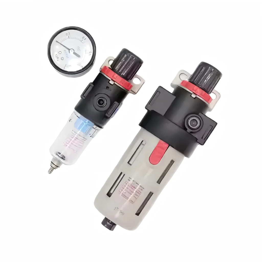
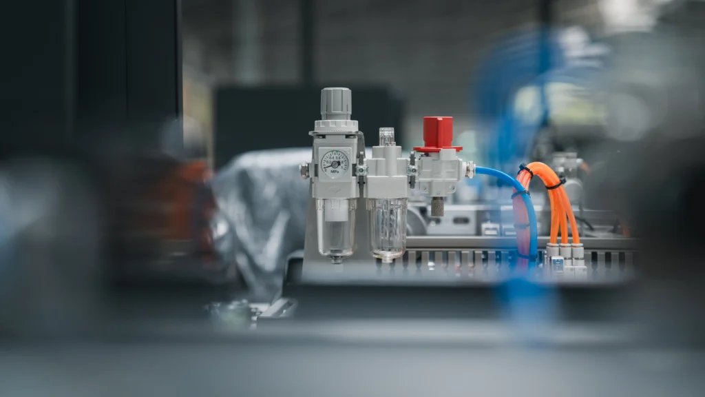
Installing a pressure regulator and air source filter at the outlet of an air compressor is not an option, but a basic guarantee for the protection of all downstream pneumatic tool accessories.
Over-pressure surge will quickly destroy the O-ring and the blades of the vane air motor inside the tool. Moisture & particulate contamination will cause corrosion of internal metal parts within a few weeks in a humid environment, thus greatly shortening the tool life.
Suggested installation location: The filter-regulator Unit (FR Unit) is installed within 1 meter from the outlet of the air compressor, so that the water can be fully trapped before entering the downstream gas path. If a variety of tools share the same gas path and the required air pressure is different, an inline flow restrictor can be installed separately on each branch for independent pressure regulation.
ANRUK pneumatic regulator series output pressure adjustable range of 0-10 bar, equipped with a visual pressure gauge, provides panel-mount and pipe-mount two configurations, suitable for workshop workbench and automated production lines.
Troubleshooting for regulators and filters
Failure phenomenon: the output pressure of the regulator has been set, and the operation of the tool is still unstable.
Causes and countermeasures: regulator rated flow may be insufficient. When all downstream tools are running at the same time, the total CFM requirements must not exceed the rated flow capacity of the regulator.
Fault phenomenon: water marks or rust marks appear inside the pneumatic tool or in the trachea.
Causes and countermeasures: daily discharge of air compressor air tank condensed water; replace the filter element every 3-6 months. It is recommended to install a refrigerated air dryer upstream of the filter in high humidity areas.
Step 7: The system is pressurized and all fittings are subjected to soap leak test
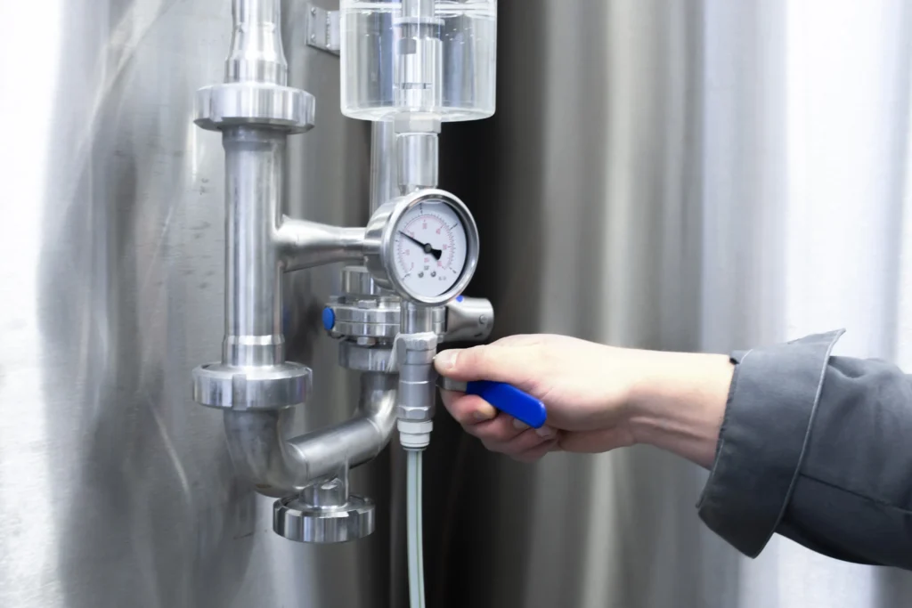
Before operating any tool, the entire gas path system should be pressurized to normal operating pressure, and then all fittings, hose ends, regulator interfaces, and solenoid valve inlet and outlet should be sprayed with soapy water. If there is a bubble, it indicates that there is a leak, which needs to be dealt with immediately.
This step is critical: a leak hole with a diameter of 1/16 inches (about 1.6 mm) loses approximately 25 CFM of compressed air per minute at 100 PSI operating pressure. This leakage is equivalent to the amount of air required to continuously drive a medium-sized impact wrench at full load, and will cause the air compressor motor to continue to operate unnecessarily, thereby significantly increasing energy consumption and mechanical wear (Source: US Department of Energy, Compressed Air Challenge). After confirming that there is no leakage, it can be put into production.
Conclusion
The key to the correct selection of pneumatic accessories is to accurately match the parameters, including pressure (PSI), flow (CFM), thread size and hose diameter, rather than relying on subjective speculation. According to these seven steps, the gas path system can stably output full load air pressure to each tool without airflow limitation or energy waste.
Does this guide help you solve practical problems? Please leave a message below, describing your specific tool model and usage scenarios, and I will reply one by one. If the content is useful to you, you are also welcome to forward it to colleagues or friends who are building the first gas system.
The products described in this guide can be found on the official website of Wenzhou Angrui Machinery Co., Ltd. The company produces pneumatic fittings, PU pipes, pneumatic hoses, air pressure regulators, solenoid valves and pneumatic cylinders, and has passed ISO, CE and RoHS certification.
What kind of pneumatic accessories do you need at least to build a gas path?
At least three kinds are needed: a set of matching quick-connector fitting and male plug, a pneumatic hose with a suitable diameter, and a set of filter-regulator units. These three can ensure that the tool can obtain clean and stable compressed air. If the filter pressure regulating component is omitted, the water and pressure shock will damage the internal seal of the tool within a few months, and the maintenance cost is much higher than the investment of the fitting itself.
Can NPT and BSP connectors be mixed in the same gas path system?
No. NPT and BSP threads do not have interchangeability. Even if the nominal size is similar, forced mixing will lead to thread damage and leakage. Although the conversion fitting can be used, there is an additional potential leakage point for each additional conversion point. The best practice is to unify the thread standards at the design stage.
What is the main difference between a pneumatic hose and a pneumatic tube?
Pneumatic hose is a multi-layer composite flexible structure marked by inner diameter (ID), which is used to transport high-pressure gas to handheld tools, focusing on flexibility and impact resistance. Pneumatic tubing is a semi-rigid structure with outer diameter (OD) marked, which is used to fix the internal alignment of the equipment, focusing on dimensional accuracy and joint fit. PU pipe is the mainstream pipe of automation, rubber pipe and PVC hose are more used in the workshop environment with high flexibility requirements.
How often should pneumatic accessories be inspected?
It is recommended to carry out visual inspection every three months. The rubber hose should be replaced immediately when there are surface cracks, bulges or creases. The lock ball of the female fitting of the quick-connect fitting is obviously worn, or the lock slot circle of the male plug is passivated, and the whole set should be discarded. Otherwise, the worn joint may eject the male plug under air pressure, causing personal injury.
How many PSI should the pressure regulator be set at?
The optimal working pressure of most handheld pneumatic tools is 90-100 PSI. Increasing the pressure will not increase the power in equal proportion, but accelerate the wear of seals and motors. Precision pneumatic tools should be adjusted to 40-70 PSI. The final setting value should be based on the recommended pressure on the tool nameplate.