Five-Step Selection Method (Quick Answer)
The core of the pneumatic cylinder sizing calculator is to convert the physical law “Force = Pressure×Area” into a cylinder diameter bore that can be directly used for ordering. Before using any selection tool, the entire process can be summarized into the following five steps:
- Confirm the load force: add the load weight, friction, and gravity in the vertical lifting condition to obtain the total thrust that the cylinder must output.
- Increased safety margin: the conventional push-pull motion multiplied the calculation result by 1.25; clamping and pressing conditions are multiplied by 1.5 or higher coefficients.
- Determine working pressure: 6 bar (about 87 psi) in most factories; the actual working pressure value should be read at the regulator.
- Calculate the cylinder bore: Substitute D=√(4F÷πP) to obtain the minimum piston diameter.
- Rounding up to the standard cylinder diameter: select the next ISO standard size (32,40,50,63,80,100 mm), and then determine the stroke and piston rod.
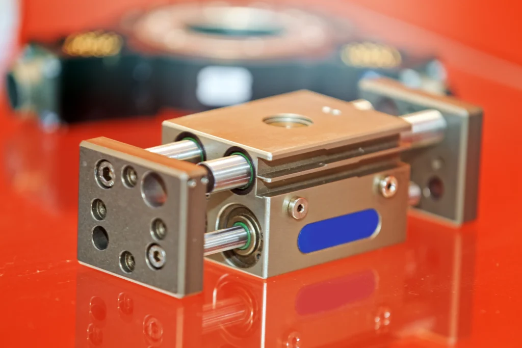
Many engineers select cylinders only by rough estimation, resulting in stalled clamps during the ramping stage of production capacity. Reading this article, you can not only operate the pneumatic cylinder sizing calculator, but also understand every variable behind it. In this way, the results given by any selection tool will become a decision-making basis that you can clearly explain. The ultimate goal is to obtain a pneumatic cylinder with the correct matching of cylinder diameter and stroke, to achieve the required thrust under the real line pressure, and to leave a safety margin.
What You’ll Need to Prepare Before Pneumatic Cylinder Selection
Overview of the scheme-3 paths for pneumatic cylinder diameter from fast to rigorous:
- Input the value into the online pneumatic cylinder force calculator, 10 seconds to get the answer;
- Refer to the force-factor table in the manufacturer’s sample, and match the corresponding cylinder diameter according to the load;
- Manual calculation formula – This is the only path that can fully incorporate the effects of friction, pressure drop and buckling (buckling of compressed members, not “buckles” ). The manual calculation takes only a few minutes, which is also the method used in this guide, because the accuracy of the calculator depends on the quality of the input data.
The specific operation requires only four inputs:
- Load force: The weight or resistance per Newton (N) or pound (lb) that needs to be moved.
- Available pressure: the gas source pressure after the pressure is stabilized by the pressure reducing valve, unit bar or psi.
- Stroke length: the moving distance required for the application.
- Installation orientation: horizontal, vertical or inclined, gravity will change the calculation results.
Prepare a calculator (or smartphone), the formula below, and a manufacturer’s cylinder bore meter, and the tools you need are complete.
Pneumatic Cylinder Bore Calculation Step-by-step
Step 1: Calculate the required force
Firstly, determine static force. When pushing horizontally, the required thrust is equal to the load weight plus friction; gravity should also be included in vertical lifting: F=m×(a+9.81). For example, a 100 kg load is lifted at an acceleration of 1 m/s², and the required thrust is F = 100×(1+9.81) = 1081 N. This is the original target value before any safety margin is applied.
Step 2: Apply a safety factor
The theoretical force cannot be completely output in practice. Only seal friction will consume about 5-15% of the output, so the actual cylinder can only reach about 85-90% of the theoretical thrust. The industry rule of thumb is to increase the thrust by at least 25% on the basis of calculated values; clamping and pressing conditions usually need to be increased by 50% or more. Before determining the cylinder diameter, the value of the first step is enlarged according to this ratio.
Step 3: Confirm the working pressure
The thrust is linear with the pressure, so this input parameter is very important. Most pneumatic systems are designed at 100 psi (about 6.9 bar). In actual operation, 80-90 psi is common, and the available range is 60-120 psi (4-8.3 bar). Please set and verify the actual pressure value at the pressure regulator – if this value is determined by estimation, it will lead to deviations in all subsequent calculation results.
Step 4: Solve for bore diameter
The formula F=P×A is transformed into A=F÷P, and then the area is converted into diameter. The pneumatic cylinder sizing calculator automatically completes this deformation process, but understanding the calculation principle helps you to verify the rationality of the calculation results.
When the SI unit is used, the combined formula is D=√ (4F÷πP). Substitute the 1081 N target value at 6 bar (600,000 Pa): D=√(4×1081÷(π×600,000)) = 0.0379 m = 37.9 mm. (If inch units are used: first, the area in 2 is calculated, and then the diameter is obtained by √(area×1.1284.))
Step 5: Round up and select the cylinder
The value of 37.9 mm is between the two standard cylinder diameters, so it must be rounded up to the next available size – here is the ISO cylinder diameter of 40 mm. The marginal cost of choosing a slightly larger cylinder is much lower than the loss that may be caused by insufficient thrust.
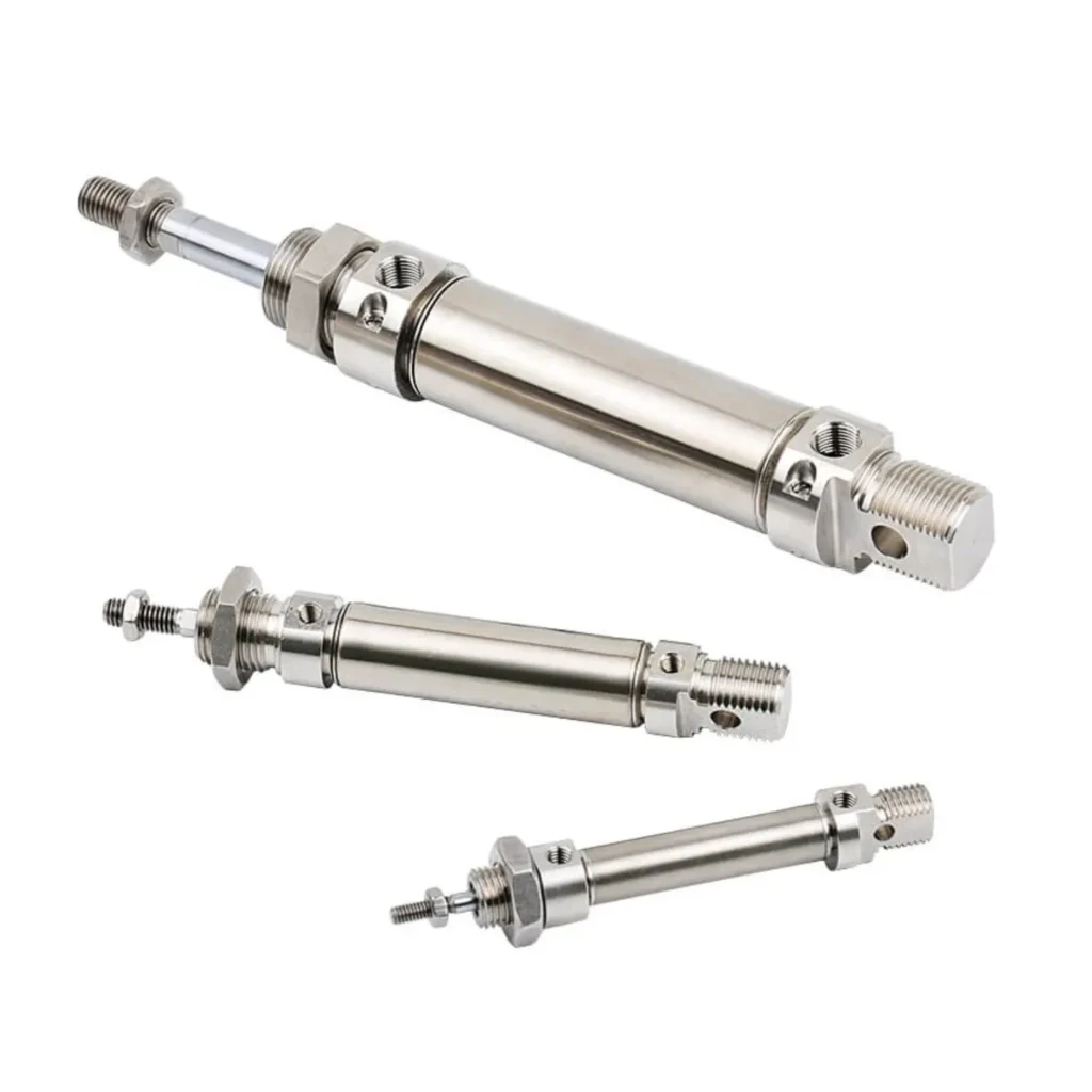
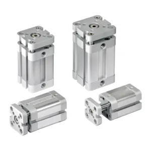
Matches your cylinder bore values to the actual product range, such as ANRUK’s Standard Pneumatic Cylinder ISO 15552 Series for full-size applications, Compact Pneumatic Cylinder ISO 21287 Series for space-constrained applications, and Min/Round Pneumatic Cylinder ISO 6432 Series for light-load applications. Firstly, the stroke is determined according to the application requirements. Finally, the size of the piston rod is selected according to the buckling resistance.
Extend vs. Retract Force
Since the piston rod occupies part of the effective area of the piston in the return stroke, the pull force is always less than the push force. The following table shows the difference at 100 psi:
| Bore | Rod | Extend (push) force | Retract (pull) force |
|---|---|---|---|
| 2″ (50 mm) | 5/8″ | ~314 lbf | ~283 lbf |
| 4″ (100 mm) | 1″ | 1257 lbf | 1178 lbf |
| 6″ (150 mm) | 1-3/8″ | 2827 lbf | 2678 lbf |
A pneumatic cylinder with a cylinder diameter of 4” and a rod diameter of 1” outputs 1257 lb when extended, and only 1178 lb when retracted. When the working stroke is in the stretching direction, this difference needs to be considered.
Troubleshooting of common selection errors
The gauge pressure is regarded as differential pressure: backpressure will be generated on the exhaust side during the movement. For dynamic load, the derate should be reduced by 20-40 % before calculating the cylinder diameter. Taking a 30 % reduction in 100 psi workshop air supply as an example, about 70 psi is actually available.
Ignore the influence of the piston rod when pulling the stroke: only according to the push force selection may lead to insufficient thrust during retraction. When the load hinders the retraction operation, the piston rod area must be deducted.
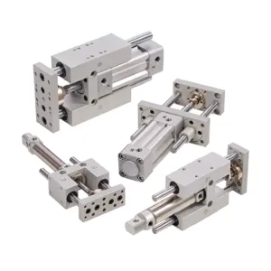
Long stroke without buckling check: even if the thrust calculation is correct, the pneumatic cylinder may still be bent under long stroke or side load. The diameter of the piston rod should be increased, the stop tube should be installed, or the guided/slide pneumatic cylinder should be used for the side load condition.
Select the Correct Cylinder with ANRUK
It should be done before choosing a pneumatic cylinder: determine the thrust, increase the safety margin, confirm the working pressure, calculate the cylinder diameter, and round up to the standard size. After mastering the five steps of the pneumatic cylinder sizing calculator, do you make your application calculation clearer? Welcome to write down the load and pressure values you are dealing with in the comment area, and please share this guide with friends who still rely on experience. When determining the pneumatic cylinder model, you can browse the complete ANRUK Pneumatic Cylinder Series.
FAQ
How to calculate the bore size of the pneumatic cylinder?
The required thrust is divided by the available pressure to obtain the piston area (A=F÷P), and then the formula D = √(4A÷π) is converted to the diameter. The cylinder diameter is the diameter that can provide enough area to meet your required thrust.
What is the formula of pneumatic cylinder force?
The thrust is equal to the pressure multiplied by the piston area: F=P×A, which is a direct application of Pascal’s Law. When extending, the area is the complete piston surface (πD²/4); the area of the piston rod (π(D²−d²)/4) should be subtracted when retracting.
How much safety factor should be added to the selection?
The general motion condition should be added at least 25% on the basis of the calculated load, because the seal friction and pressure drop will reduce the theoretical output. Clamping, pressing and key applications should be 50 % or higher. The actual cylinder can only output about 85-90 % of the theoretical thrust.
Does stroke length affect the selection of cylinder diameter?
The stroke does not change the conversion relationship between thrust and cylinder diameter, but the long stroke will increase the buckling risk.
Note: This guide covers the selection basis of general industrial applications. For safety-critical or high cycle systems, please use the manufacturer’s datasheet to approve the final specifications.