After reading this article, you will be able to judge a faulty pneumatic solenoid valve in five minutes, and determine whether it is the cleaning, rewiring, or direct replacement. I am writing this solenoid valve troubleshooting guide because I’ve seen too many valves that are already intact are removed and scrapped. These problems can be solved in minutes with a multimeter and a 5-micron filter.
Fast Repair: 7 Steps to Pneumatic Solenoid Valves Troubleshooting
This set of pneumatic solenoid valves troubleshooting process is carried out in the order from low cost to high cost, from external to internal, so you rarely unnecessarily scrap a valve that only needs to replace the filter:
- Confirm the control signal and voltage: the voltage should be within ±15% of the rated value in the coil terminal measurement.
- Press the manual override button: if the spool changes direction with it, the fault is on the electrical side, not the mechanical side.
- Using a multimeter to measure coil resistance: display “OL” (open/excessive range) indicates that the coil is open, and the resistance value is close to zero indicates a short circuit.
- Verification of gas supply: the externally piloted spool valve usually requires a pilot pressure of about 2.5-4 bar (35-58 psi) to change direction.
- Check the cleanliness of the air source: pollution, improper voltage and poor installation of the three, accounting for about 80% of the pneumatic failure.
- Cleaning the spool and seat: if there is still stuck, replace the worn O-ring or seal.
- Replace the coil or the whole valve: only when the electrical and pressure inspections are passed, but the valve still cannot be reversed.
What Do You Need to Prepare Before Checking a Pneumatic Solenoid Valve?
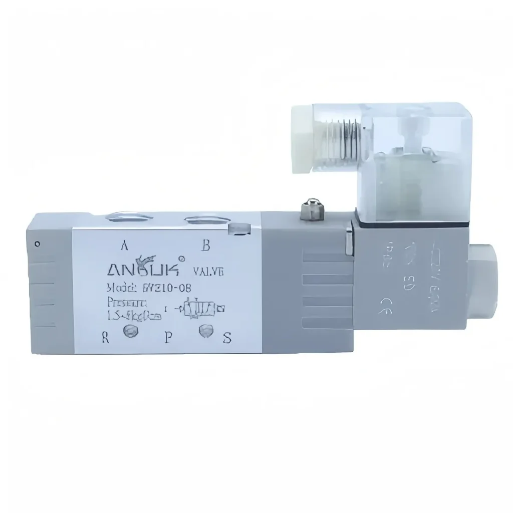
Before starting the diagnosis, please determine the direction of the investigation. Since most faults can be classified into the following three categories, choosing the right path saves the most time:
- Electric priority (using multimeter and manual reversing button): this is the fastest way to diagnose, about half of the “no commutation” fault can be solved before touching the valve body.
- Ventilation cleaning (use of filters, manual exhaust and swabs): suitable for spool stuck, slow reversing and air pollution problems.
- Replace new coil or whole valve: when the coil is burned or the valve body is mechanically damaged, it is used.
Tools and materials to be prepared: multimeter, insulating gloves and goggles, pressure gauge, a spare 5 micron filter element, small inner hexagonal wrench or screwdriver, isopropyl alcohol and dust-free cotton swab, compressed air blow gun, and matching spare coil or seal kit. Since the energized coil will produce a high-voltage spike at the moment of power failure, do not touch the two terminals by hand when disconnecting the circuit.
Common Pneumatic Solenoid Valve Failure: Fault and Response Method Table
Please match the symptoms with the most likely causes before dismantling. Since the same coil or pollution problem will be manifested as a variety of different symptoms, this fault-finding chart can help you directly determine the countermeasures that should be prioritized:
| Fault | Most likely cause | First fix |
|---|---|---|
| No actuation, no click | Open coil, lost signal, or blown fuse | Test voltage at terminals, then coil resistance |
| Clicks but won’t shift | Stuck spool or low pilot pressure | Press override, raise pilot to 2.5–4 bar, clean spool |
| Won’t fully close/leaks air | Debris on the seat or worn seals | Blow out the seat, replace O-rings |
| Buzzing or humming (AC) | Loose top nut or dirt in the armature | Tighten the nut, clean the armature tube |
| Overheating or burnt smell | Wrong voltage or continuous duty | Verify voltage ±15%, use a continuous-duty coil |
| Sluggish or inconsistent shifting | Contaminated or wet air | Fit a 5-micron filter, drain condensate |
Pneumatic Solenoid Valves Troubleshooting: Step-by-step Operation
Step 1: Verify the control signal and voltage
Checking starts from the controller, not from the valve. With the PLC diagnostic function or multimeter, it is confirmed that the output signal is indeed delivered to the correct coil. Then, the voltage of the coil terminal is measured when the valve is energized by the command. The voltage reading of a 24V DC coil should be in the range of 21.6-26.4V, and the 12V DC coil should be in the range of 10.8-13.2V. Due to the voltage drop caused by the long cable, reading below the above interval usually points to the line problem, rather than the valve itself failure.
Step 2: Test the coil with a multimeter
First disconnect the power supply, and then interrupt the coil from the circuit. The multimeter is adjusted to the resistance block, and the pen contacts the two terminals. The resistance of general AC/DC coils is usually between 20-100 Ω, of which 12V DC coils are about 3-6 Ω and 24V DC coils are about 15-30 Ω. The “OL” (infinity) reading indicates that the winding is open, and the resistance close to zero indicates a short circuit; the coil needs to be replaced in both cases.
| Coil rating | Healthy resistance | Energized voltage band |
|---|---|---|
| 12 V DC | ~3–6 Ω | 10.8–13.2 V |
| 24 V DC | ~15–30 Ω | 21.6–26.4 V |
| Generic AC/DC | 20–100 Ω | within ±15% of rating |
* Precautions: before determining the scrap, it is necessary to confirm the coil parameters with reference to the nameplate or datasheet. “OL” means open circuit, and resistance close to zero means short circuit, both of which should be replaced by coils.
Troubleshooting: common electrical errors
Live measuring coil: the measuring coil will damage the multimeter and cause electric shock in the energized state. Be sure to disconnect the power supply first, and then disconnect the coil from the circuit.
Ignore the manual reversing button to provide clues: if the manual reversing button is pressed to reverse the valve, and the coil is measured to be open, there is no need to continue to check the spool, and the coil can be replaced directly.
Voltage type error: connecting the 24V coil to a higher power supply will cause it to burn quickly; before energizing, it is necessary to confirm whether the coil is AC or DC on the nameplate.
Step 3: Check air supply and pilot pressure
After eliminating the electrical side problems, turn to check the gas path. Connect the pressure gauge to the air inlet to confirm that the set value of the regulator is within the working pressure range of the valve; most workshop systems operate at 0.4-0.6 MPa. For internally piloted valves, if the differential pressure is too low (usually lower than the pilot window of 0.1-1.5 bar), the spool will only be reversed to half of the position. It is necessary for external pilot valves to verify whether the independent pilot line provides a pressure of 2.5-4 bar.
Step 4: Clean the spool and replace seals
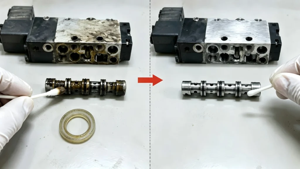
If both the electrical inspection and pressure inspection pass, but the valve is still stuck, the valve core is likely to be stuck by the paint film (varnish, lacquer deposits formed by oil oxidation) or impurities. Close the gas source and empty the residual pressure, remove the valve body, and clean the valve core, valve bore and valve seat with isopropanol and dust-free cotton swab. Blow through the pilot orifice, because even a particle may block it. Replace hardened or swollen O-rings after cleaning: in dry, oil-free air, the seal loses oil film and adheres to the valve body during shutdown.
Troubleshooting: Mechanical common errors
Omit the filter step: cleaning the contaminated valve without installing an upstream 5 micron filter will cause the next jam to occur again very quickly.
Reuse stretched seals: old O-rings are difficult to reposition and should be replaced with a new seal kit when the valve body is opened.
Excessive tightening of fittings: excessive torque will lead to cracking of the valve body and new leakage; it should be tightened according to specifications, not by hand feeling.
Step 5: Replace the coil or valve
When the coil is measured to be open or short circuit, replace a coil whose voltage and frequency are completely matched. If the valve body is cracked or the valve hole is scored, the entire valve is replaced directly instead of being repaired repeatedly. For pneumatic slide valves, a reliable pilot-operated 4V series 5/2 valve or pilot-operated 4/5-port solenoid valve can usually be replaced directly. It can be selected according to the diameter and flow rate in the whole series of ANRUK solenoid valves.
Prevent the Next Failure of Pneumatic Solenoid Valve
More than 70% of the pneumatic solenoid valve failure is not the product itself defects, so preventive measures can be effective quickly. The valve is supplied with clean and dry air through the FRL units. A 5 micron air filter is installed in front of each machine to control the voltage within ± 15%, and a pressure switch is used to detect an early decrease in the supply pressure. Standby valves should be energized 5-10 seconds per month to prevent seals from becoming rigid.
How to judge whether the pneumatic solenoid valve is damaged?
Electrify and listen to the click sound, or press the manual commutation button. If there is no click sound and no commutation, it usually means that the coil is damaged or the spool is stuck. The measurement with a multimeter can confirm that the reading of the coil open circuit or short circuit can prove that the fault is on the electrical side rather than the mechanical side.
What is the resistance value of the pneumatic solenoid valve coil?
This depends on the specific coil model, so be sure to check the nameplate first. As a reference, the 12V DC coil is about 3-6 Ω, the 24V DC coil is about 15-30 Ω, and the resistance of many AC and DC coils is in the range of 20-100 Ω. Readings of OL or close to zero mean that the coil needs to be replaced.
What is the minimum working pressure of the pilot-operated solenoid valve?
Most internal pilot-operated slide valves require a pressure difference in the range of 0.1-1.5 bar to reverse. The spool can only be partially reversed below this value. Externally piloted models typically require a pressure of 2.5-4 bar on a stand-alone ducted path, so be sure to check the data sheet for the series you use.
Can the stuck pneumatic solenoid valve be cleaned but not replaced?
Usually. If the electrical test is normal, the valve core is not moving, usually caused by impurities: open the valve body, clean with alcohol, blow through the pilot hole, and replace the seal. However, if the valve hole has a bright color strain, the internal leakage will be too large, and the replacement of the whole valve is a reliable method.
Botton Line
The above is the complete on-site process: from a 10-second “click test” to a direct replacement of a new item. Does this pneumatic solenoid valve troubleshooting practice help you put the valve back into use? If a specific fault is still not resolved, please write down the symptoms and your measured coil resistance reading in the comments area.