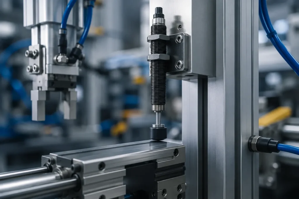
After installing the size-matched pneumatic shock absorber, the motion load that would have slammed the end cap violently can now be stopped smoothly and repeatedly. This guide is based on ANRUK’s clear understanding after dealing with hundreds of selection consultations: the three parameters of quality, speed, and cycle frequency directly determine whether a buffer can continue to work for several years or fail within a few weeks. Accurately calculate these parameters, the subsequent steps are only basic operations.
Quick Answer: Pneumatic Shock Absorber Selection Completed in 7 steps
In order to ensure accurate selection and avoid errors caused by missing steps, please strictly follow the following order:
- Määritä kuorma: record the mass of motion (kg), impact velocity (m/s) and installation direction (horizontal, vertical or rotary motion).
- Laske kineettinen energia: the formula KE = ½mv², which is commonly used in the engineering manuals of major manufacturers, is adopted.
- Superimpose drive energy: the thrust force of the cylinder or motor; the total energy per cycle of a single cycle must also be included in the vertical drop.
- Multiplicate of cycle rate: the total energy per cycle is multiplied by the number of cycles per hour to obtain the energy per hour, which is then checked with the thermal rating of the buffer.
- Apply safety factor: when the cycle frequency exceeds 240 times per hour, about 30% of the margin is increased on the basis of kinetic energy.
- Match stroke and model: make the rated energy absorption capacity greater than the total energy, while maintaining the deceleration below about 8 g.
- Set the physical stop: the hard block is set at 90% -95% of the stroke to prevent the buffer from touching the bottom, and then the test is carried out on the device.
What Do You Need to Prepare Before Choosing Pneumatic Shock Absorber?
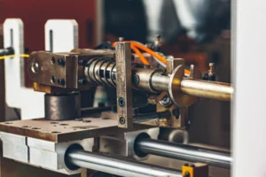
By watching the video, you can first understand how the high-speed cylinder reduces its speed at the end of each stroke, which helps you understand why you need a pneumatic shock absorber. Before comparing types, collect complete input parameters and determine which type of pneumatic shock absorber is suitable for your production line. There are three options, please consider first:
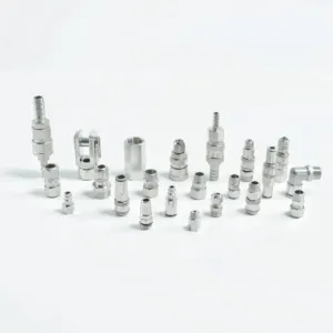
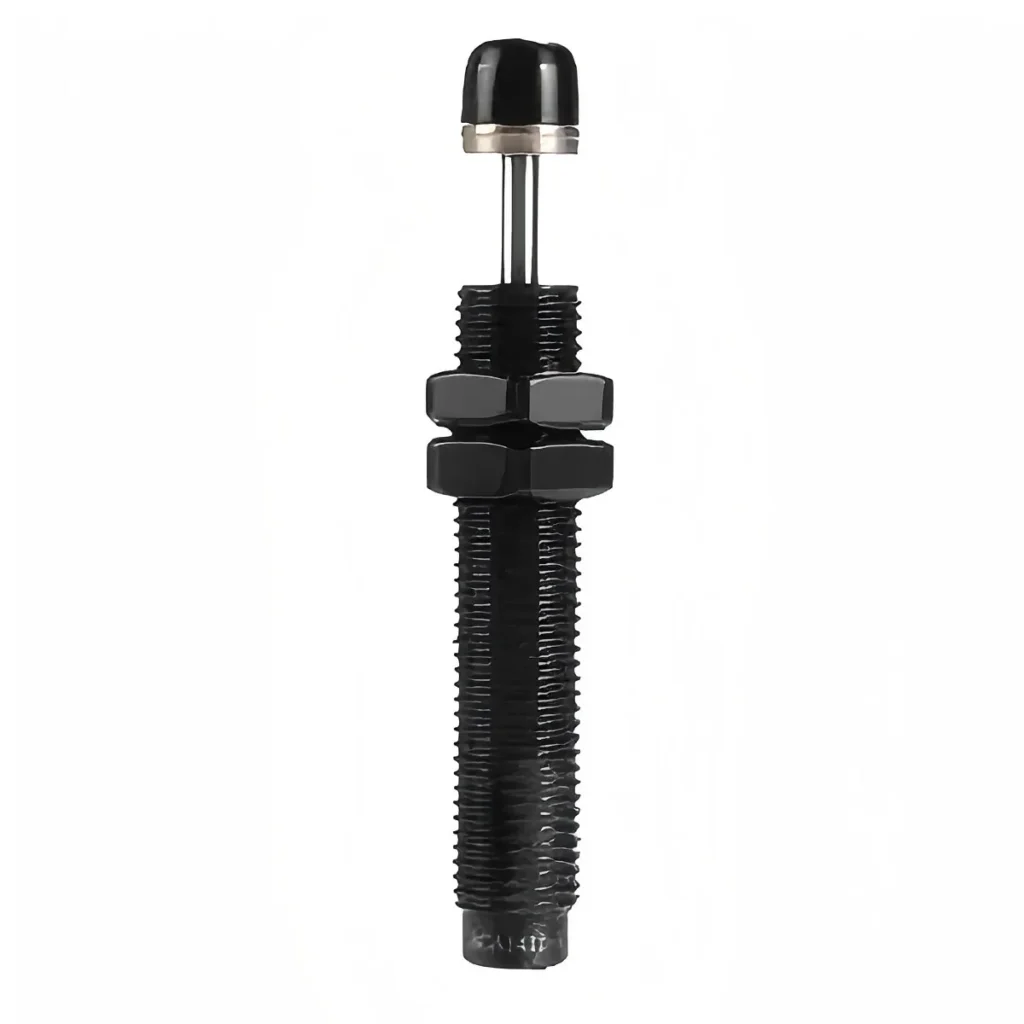
- Self-compensating pneumatic shock absorber: fixed-orifice, without adjustment, can adapt to a certain range of mass and speed changes. For mixed or variable loads, it is a practical default option, with the disadvantage of relatively high reaction force.
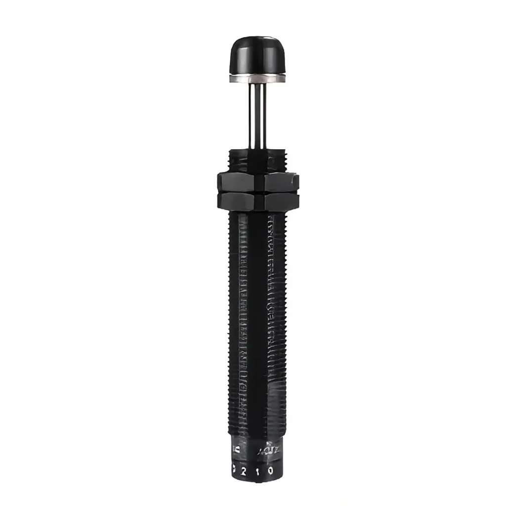
- Adjustable pneumatic shock absorber: equipped with adjustable knobs or screws, the technician can accurately adjust the damping force to a fixed load. It is suitable for robotics and test benches with constant working conditions but high accuracy requirements.
- Mechanical or elastomer stop: as a simple buffer element suitable only for low-energy operations, it stores energy and may produce rebounds, so it is not suitable for high-speed pneumatic cylinders.
After determining the type, please collect the following data: motion mass (kg), impact velocity (m/s), thrust (N), number of cycles per hour, and available installation space. Usually, a digital caliper, cylinder thrust specification table and load drawings, is all the tools and information you need.
Selecting Pneumatic Shock Absorber Step-by-Step: Sizing & Stroke
Step 1: Measure the moving load
Please start from the effective quality, not only on the basis of static net weight, because the conveyor belt, fixture and tooling and other components will be accumulated to the buffer needed to brake on the object. Each component moving with the slide is weighed or summed separately, and the total mass obtained is the load that the pneumatic buffer really needs to stop. Since the pneumatic drive speed often reaches more than 3 m/s, even if the mass is not large, it also contains considerable energy. In this step, the estimation is low, which will affect the accuracy of all subsequent calculations. At the same time, the direction of motion is recorded: gravity needs to be included in the calculation under vertical falling conditions, and horizontal sliding does not need to be included.
Step 2: Calculate energy per cycle
Next, the motion parameters are converted into energy values. The kinetic energy is calculated according to KE = ½ mv², but the complete energy value of the pneumatic buffer needs to be included in the driving energy. When the cylinder continues to output thrust during the deceleration process, the product of thrust and stroke needs to be superimposed; if it is a vertical motion, the product of the weight and the stroke needs to be added to account for the work done by gravity. The sum of the three is the single cycle energy, which is the only key parameter to determine the buffer capacity level. Conservative estimation is always more reliable than optimistic estimation.
Step 3: Check energy per hour & stroke
Pneumatic shock absorber converts shock into heat, so thermal load is as important as single shock energy. Multiply the single cycle energy by the number of cycles per hour, and then confirm that the hourly rated energy absorption value of the candidate model is higher than that value. At the same time, the selected stroke length: the longer the stroke, the same energy is absorbed over a longer distance, the lower the peak force, and the slower the deceleration process. For most industrial automation scenarios, the deceleration should be controlled within about 8 g to protect electronic components, reduce noise and limit structural stress.
Step 4: Apply safety factor & match model
Finally, a safety margin needs to be set aside. When the cycle rate exceeds 240 times per hour, an additional increase of about 30% is added to the kinetic energy. For extremely high frequency conditions, it is recommended to consult suppliers. Then a pneumatic shock absorber with a rated energy absorption capacity significantly higher than the adjusted total energy is selected. If the load changes, choose the self-compensating type pneumatic shock absorber; when the precise setting of a single fixed load is required, choose the adjustable type pneumatic shock absorber, also the mounting thread and the body diameter are confirmed to match the equipment.
Troubleshooting of Installing Pneumatic Shock Absorber
Even if the calculation is rigorous, the problem often occurs in the installation process. Please pay attention to the following recurring errors:
Touch the bottom (cause metal impact sound)
The reason is that the impact energy exceeds the buffer capacity, or no limit block is set.
Countermeasure: Set physical stop at 90%-95% of the trip and recheck whether the total energy value matches the rated value.
Load rebound
The common reason is the use of springs or rubber stoppers rather than real pneumatic shock absorbers, or the selected model is too large relative to the actual load capacity.
Countermeasure: Replace the self-compensating buffer with rated parameter matching.
Buffer overheats or leaks prematurely
The reason is that the hourly energy accounting is ignored.
Countermeasure: recalculate the heat load, increase a capacity level, or reduce the cycle frequency.
Learn More about Pneumatic Shock Absorber with ANRUK
Choosing a pneumatic shock absorber depends on several key parameters: mass, speed, driving force and cycle frequency, and then checked with the rated capacity and stroke. Is the step analysis of this article helpful to you? If a step for your device is still not clear, please leave the load parameters in the comment area or ota yhteyttä ANRUK-tiimiin; it is also suggested that this article be shared with colleagues who are responsible for dealing with the problem of production line impact sound.
FAQ
How does the pneumatic shock absorber work?
When a moving load pushes the piston rod inward, air or oil is forced through an orifice to convert kinetic energy into heat and escape into the atmosphere. It is this controlled resistance (rather than rigid block) that achieves a smooth and buffered stop.
What is the difference between adjustable and self-compensating?
The adjustable type adjusts the damping to a precise load through a knob, which is suitable for occasions with constant working conditions. The self-compensating type adopts fixed orifices, which can automatically adapt to the quality and speed within a certain range, so it is a more reliable default choice for hybrid production lines.
How to choose the appropriate stroke length of a pneumatic shock absorber?
The longer the stroke, the same energy is distributed over a longer motion distance, and the lower the peak deceleration force. Choose the shortest possible stroke while ensuring that the deceleration is less than about 8 g, a range that protects electronics and suppresses noise in most industrial scenarios.
Can a pneumatic shock absorber be used for vertical drop?
Yes, but gravity must be included in the energy calculation: in addition to kinetic energy, the product of the load weight and the stroke must be added. The energy of vertical movements may be more than twice that of horizontal movements, so higher capacity levels are often required.